Selecting Shapes and Holes
There are two ways to select shapes and holes in the Drawing & Data tab.
| 1) | Using the Shapes browser. |
| 2) | Using the mouse pointer. |
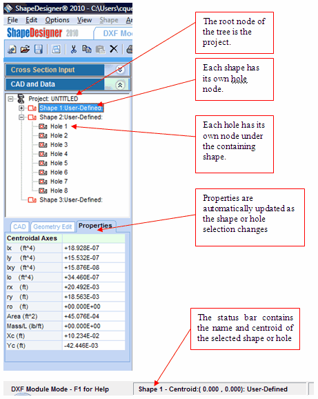
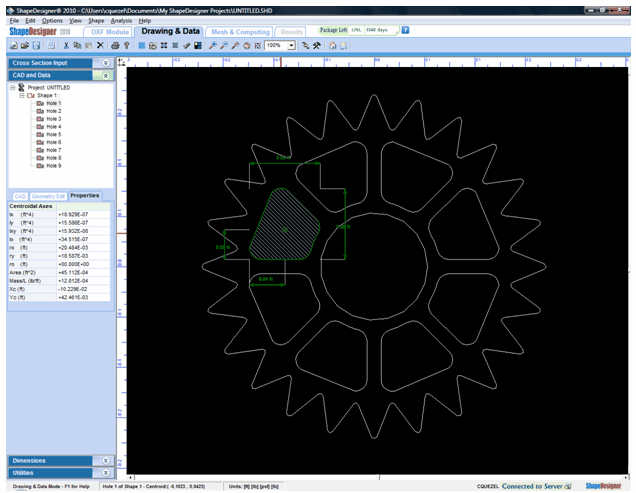
To select a shape using the Shapes browser, select the CAD and Data tab from the toolbox and click on the desired shape in the tree list. The tree list is a hierarchical view of the current project. The project is the root node of this tree. Shapes are the following nodes. Each shape node contains its hole nodes. The selected shape or hole is highlighted with a white hatching and a green contour in the drawing area. Basic dimensions and centroid position are also displayed in the drawing area and in the status bar. Other properties, located under the Properties tab, such as area and inertias are also dynamically updated.

To select a shape using the mouse pointer, move the pointer over the shape or the hole in the drawing area then press the left mouse button. If the CAD and Data tab is open, then its information will be updated just as if you had used the tree view to perform your selection.
If the selection is ambiguous, that is more than one shape or hole could qualify as being selected, every subsequent click will select a different ambiguous shape. This is useful for selecting shapes within shapes. See the “Creating Shapes within Shapes” section of this document for more details on selecting nested shapes.

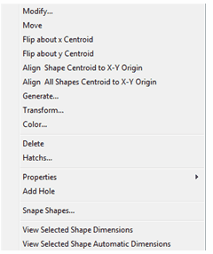
When a shape or hole is selected, the Shape menu becomes available. You may also access the Shape menu by right clicking the mouse button.
