|
Shear in Built-Up Beams (Connectors calculation) |
  
|
|
Shear in Built-Up Beams (Connectors calculation) |
|
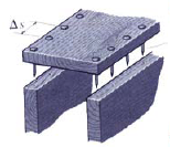
There are a number of important applications of beams where welds, glue, rivets, bolts, or nails are used to join two or more structural components to form a single beam. Several examples of such built-up beams are used in the industry. They are:
| 1. | a glued-laminated timber beam |
| 2. | a welded plate girder |
| 3. | a wooden box beam constructed of several planks nailed together |
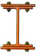
| 4. | a beam with reinforcing flange plates bolted to the basic beam. |
In such cases it assumed that the beam acts as a unit (e.g., plane sections remain plane) and that the joining medium (nail, weld, bolts, etc.) is capable of transferring shear across the longitudinal junctions between component parts of the beam.
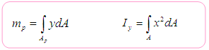
The required shear flow that must be transferred from one part of the beam to the adjacent part under the given loading condition is:
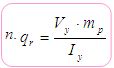 , where: n is the number of connectors/part and
For the discrete shear connectors (as bolts, discontinued weld , nails etc.), each connector having a shear–force capacity Va, are spacing along a joint at a spacing Ds, as illustrated, then the joint will fail unless:
![]()
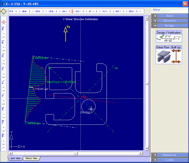
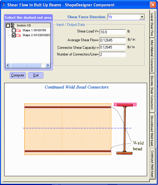
In ShapeDesigner, you can verify your design: In the Results mode window select the Design tab and then click on the Shear Flow-Built-up button from the View toolbox, and the Shear Flow in Built-up Beams dialog appears.

The local Shear Flow case

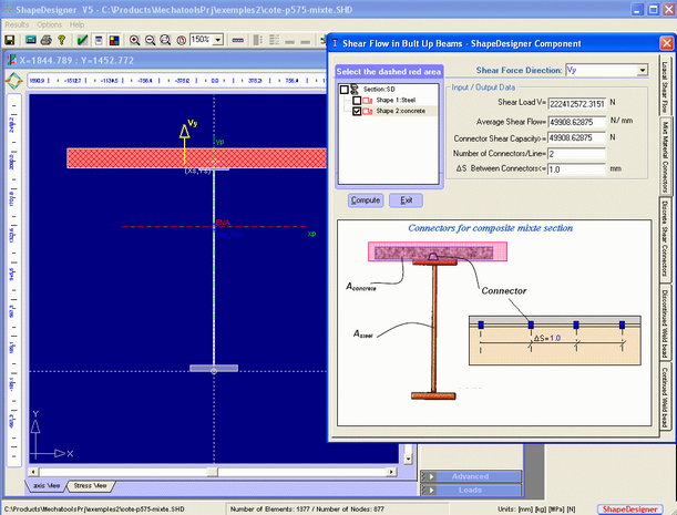
The composite action Shear Flow case

The continued welded bead case
Example of steel-concrete composite section in ShapeDesigner:
For practical examples for the use of the Shear flow built-up component see examples section in chapter 6